

Interference hunting · spectrum monitoring · direction finding — NARDA, made in Germany
Radio Monitoring and Localization: NARDA SignalShark
Detect the signal, analyze it, locate the transmitter on a map — with one instrument. NARDA SignalShark is a portable radio monitoring and localization system covering 8 kHz to 8 GHz. It combines a spectrum analyzer with 40 MHz real-time bandwidth, a monitoring receiver that measures in line with ITU recommendations, and an automatic direction finding (DF) system in a single housing. It is used handheld, in vehicles, in racks or on masts for interference hunting, spectrum monitoring, detection of illegal transmitters, signal intelligence and drone detection. This page covers every device version, the direction finding antennas, the software options and the accessories, with values taken from the manufacturer’s datasheets.
- 8 kHz – 8 GHz
- 40 MHz real-time
- Scan rate above 50 GHz/s
- 100% POI from 3.125 µs
- Automatic DF: 10 MHz – 8 GHz
- Up to 26.5 GHz with handheld antenna
- Windows 10 + Python
- MIL-PRF-28800F Class 2
- Handheld · rack · outdoor · module
Configuration, quotation, delivery and after-sales support are handled from Istanbul. For NARDA products our sales territory is Turkey.
What is SignalShark, and who uses it?
A conventional spectrum analyzer sweeps across the band; it misses a short signal unless the sweep happens to be on that frequency at that moment. SignalShark digitizes a 40 MHz wide band without gaps and computes overlapping FFTs. Pulses lasting a few microseconds, frequency-hopping transmissions and sporadic interferers are captured at their full level. Wider bands are scanned at more than 50 GHz per second.
The instrument does not stop at “there is a signal”; it also tells you where it comes from. With the automatic direction finding antenna ADFA 2 a bearing is calculated every 1.2 milliseconds, the bearings are combined on a map, and the probable transmitter position is shown as a heat map. With handheld directional antennas the same job continues on foot, indoors or on a rooftop.
SignalShark is an open platform: it runs Windows 10, executes Python scripts and third-party software on the device, is remote-controlled via SCPI and streams IQ data to the network using VITA 49.
Typical users:
- Frequency regulators and spectrum monitoring services — band occupancy, unlicensed transmissions, interference complaints
- Defense industry and armed forces — signal intelligence (SIGINT / ELINT), electronic support, jammer detection, border surveillance, detection of drone control and video links
- Police and security services — search for illegal transmitters, bugging devices and jammers; search and rescue
- Mobile operators and broadcasters — locating interference in the network, coverage measurement, 5G field measurements
- Aviation, railway, energy and critical infrastructure operators — protection of communication and navigation bands
- Research institutes, universities and system integrators — research, custom software, embedding the module in other systems
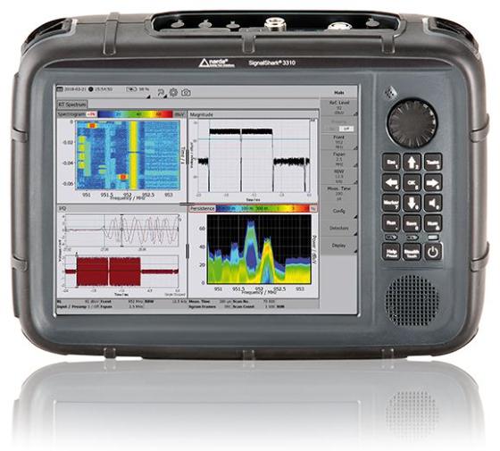
SignalShark 3310 handheld: 10.4-inch touchscreen, two hot-swappable batteries, approx. 4.1 kg.
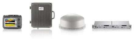
The SignalShark family: handheld, outdoor unit, ADFA antenna and rack-mount unit share the same receiver technology.
What is radio monitoring, and how is an interferer located?
Radio monitoring means observing the radio spectrum to see who is transmitting, on which frequency, with what level and from where. Regulators use it to check band occupancy and licence compliance; operators use it to protect their networks. Interference occurs when an unwanted signal degrades or blocks the reception of a wanted one: dropped calls, falling data rates, noisy radio links, remote controls that stop working. In aviation, railway and emergency communications it is a safety issue.
| Type of interference | How it arises | Typical source |
|---|---|---|
| Co-channel interference | Two transmitters on the same frequency reach into each other’s coverage area | Unlicensed or misconfigured transmitter, distant station under unusual propagation |
| Adjacent-channel interference | Energy from the neighbouring channel leaks through the filter | Wideband or overdriven transmitter, insufficient filtering |
| Harmonics and spurious emissions | A transmitter also radiates at multiples of, or outside, its operating frequency | Faulty amplifier, defective filter, poor-quality repeater |
| Intermodulation | Two or more strong signals mix in a non-linear element and create new frequencies | Shared antenna systems, corroded connections, overloaded amplifiers |
| Broadband electrical noise | Switching circuits radiate noise across a wide band | LED drivers, power supplies, motor drives, power line communication (PLC), faulty insulators |
| Intentional jamming | A band is deliberately filled with noise or a signal | Illegal jammers |
The source is found in three steps. The questions in the field are always the same: who is responsible, which signal arrives from which direction, and where is the source?
- Detect — the spectrum is scanned quickly and the disturbing signal is separated from legitimate transmissions. For short and sporadic signals, the real-time spectrum, Persistence and the spectrogram are used.
- Analyze — bandwidth, modulation and time behaviour are examined; where useful the signal is demodulated and listened to. This gives clues about the type of source.
- Localize — bearings are taken from a vehicle with the automatic direction finding antenna and intersected on the map; the last stretch is covered on foot with a handheld directional antenna.
SignalShark performs all three steps in one instrument. It replaces the NARDA IDA 2 (Interference and Direction Analyzer), which has been discontinued.
Which version and which antenna do you need?
All four versions share the same RF performance: 8 kHz – 8 GHz, 40 MHz real-time bandwidth, scan rate above 50 GHz/s. They differ in display, power supply, housing and connectivity. The choice depends on where the instrument will be and how direction finding will be done.
| Your task | Recommended version | Recommended antenna and options | Why |
|---|---|---|---|
| Hunting an interferer on foot; indoors, rooftops, narrow streets | Handheld 3310 | Active antenna handle + directional antenna 3 (400 MHz – 8 GHz); Horizontal Scan, Mapping and Localization | About 3 hours on battery; the handle’s compass logs each bearing automatically |
| Fast localization by vehicle in a city | Handheld 3310 or Remote Unit 332x | ADFA 2 (magnetic vehicle mount); Automatic DF Antenna Control, Mapping and Localization | Automatic bearings and heat map while driving; up to 130 km/h |
| Fixed monitoring station, vehicle or container rack | Remote Unit 332x | ADFA 2 on a mast; SCPI, VITA 49 | 1 HU in a 19-inch rack; four antenna inputs; operated by remote desktop |
| Unattended outdoor station, border, hilltop, rooftop | Outdoor Unit 333x | ADFA 2; PoE++ or integrated modem | IP65, fanless, −20 to +55 °C; data and power over one Ethernet cable |
| Embedding in your own system (vehicle, cabinet, OEM) | DF Receiver Module 334x | ADFA 2 or your own antenna; VITA 49 IQ streaming | Compact module; 10 – 48 VDC; designed for customer-specific systems |
| Wide-area localization with several stations | Outdoor Unit 333x or Remote Unit 332x (two or more) | ADFA 2; NSL Remote DF script | Bearings from networked devices are intersected on one map |
| Above 8 GHz: satellite links, radar, microwave links | Handheld 3310 | DF Downconverter Antenna (7 – 26.5 GHz) | One antenna for the whole range; integrated LNA and downconverter |
| Below 30 MHz: PLC, switched-mode supplies, HF interference | Handheld 3310 | Active antenna handle + loop antenna (8 kHz – 30 MHz) | Magnetic field antenna; line-borne and equipment-borne interference |
| Detailed analysis of very short, sporadic or hidden signals | Any version | IQ Analyzer option | 20 ns time resolution; recording, triggering, time-gated measurement |
| 5G base station exposure measurement | Handheld 3310 | Three-axis E-field antenna (200 MHz – 8 GHz); 5G Analyzer | Automatic extrapolation to maximum load |
Key features
The values below are taken from NARDA’s SignalShark 3310 datasheet; because the RF section is common, they also apply to the other versions.
40 MHz real-time spectrum
100% probability of intercept (POI)
The 40 MHz band is processed without gaps; FFT overlap is 75%, and 87.5% for spans of 20 MHz and below. At RBW 800 kHz every signal longer than 3.125 µs is captured with 100% probability at its full level. 1.6 million spectra are calculated per second. RBW in the real-time spectrum ranges from 1 Hz to 800 kHz.
Scan rate above 50 GHz/s
The full 8 GHz in well under a second
Bands wider than 40 MHz are observed with the scan spectrum: more than 50 GHz/s at RBW 1.6 MHz, typically 30 GHz/s at RBW 100 kHz. RBW in scan mode is selectable from 1 Hz to 6.25 MHz. A new emission inside a wide band is noticed quickly.
High dynamic range (HDR)
The weak signal next to the strong one
Preselector filters and a 16-bit digitizer make weak signals visible next to strong transmitters. The noise floor (DANL) is better than −159 dBm/Hz between 44 MHz and 3 GHz (typ. −162), the third-order intercept point (IP3) is typically +14 dBm between 630 MHz and 3 GHz. IF and image rejection are better than 80 dB.
Second receiver path and demodulation
Listen while you watch
While the spectrum is displayed, a selected channel is measured and demodulated on a separate path. Channel bandwidth (CBW) in the Level Meter is 25 Hz – 40 MHz. AM, FM, PM, USB, LSB, ISB, CW, pulse and IQ demodulation with squelch, AGC and WAV recording. CISPR detectors (quasi-peak, C-RMS, C-Avg) and EMC filter bandwidths are included.
Open platform
Windows 10, Python, SCPI, VITA 49
The instrument runs Windows 10 IoT Enterprise (Intel Atom quad core). You can write your own applications in Python and run third-party signal analysis software directly on the device. Remote control via SCPI; VITA 49 IQ streaming at sample rates up to 25.6 MHz and FFT streaming with spans up to 40 MHz.
Built for the field
MIL-PRF-28800F Class 2, IP54
Vibration, shock and transit drop are tested to MIL-PRF-28800F. Operating temperature −10 to +55 °C; IP54 with antenna attached and covers closed, IP67 in the hardcase. The 10.4-inch display can be operated with gloves. Two batteries are hot-swappable during operation; the built-in GNSS receiver (GPS, GLONASS, BeiDou, Galileo) provides position and time.
Device versions
The same receiver is offered in four housings. The rack, outdoor and module versions are also available as more powerful XT models.
Handheld 3310
Handheld, battery-powered
10.4-inch touchscreen, loudspeaker and microphone. Four switchable RF inputs: 1 × N + 3 × SMA. About 3 hours on two Li-Ion batteries. 230 × 335 × 85 mm, approx. 4.1 kg. For field teams.
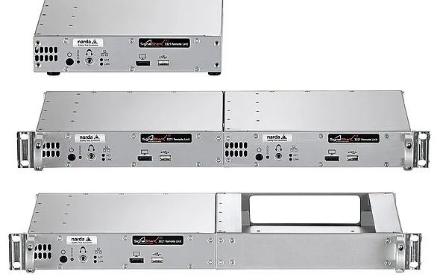
Remote Unit 332x
19-inch rack, 1 HU
No display; operated by remote desktop or an external screen. 1 × N + 3 × SMA inputs. 10 – 48 VDC. 43.5 × 220 × 204 mm, approx. 2.1 kg; −20 to +55 °C. For vehicles, containers and fixed stations. Models: 3320 and 3321 XT.

Outdoor Unit 333x
Outdoor, IP65
Fanless die-cast aluminium housing for wall or mast mounting (Ø 48 – 200 mm). 3 × N switchable inputs. PoE++, integrated modem or XT model. 151 × 356 × 353 mm, approx. 13 kg; max. 40 W.
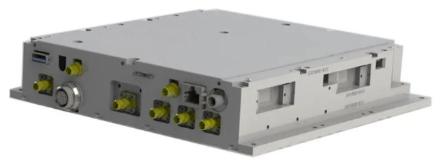
DF Receiver Module 334x
Integration module
Designed for installation in customer-specific systems. 4 × SMA switchable inputs. 10 – 48 VDC. 42.5 × 202 × 209 mm, 2375 g; −20 to +55 °C. Models: 3340 and 3341 XT.
Version comparison
| Handheld 3310 | Remote Unit 332x | Outdoor Unit 333x | DF Receiver Module 334x | |
|---|---|---|---|---|
| Where it is used | In the hand, in the field | Rack: vehicle, container, station | Outdoors: mast, wall | Embedded in another system |
| Frequency range | 8 kHz – 8 GHz | 8 kHz – 8 GHz | 8 kHz – 8 GHz | 8 kHz – 8 GHz |
| Real-time bandwidth | 40 MHz | 40 MHz | 40 MHz | 40 MHz |
| Scan rate | > 50 GHz/s | > 50 GHz/s | > 50 GHz/s | > 50 GHz/s |
| Display | 10.4-inch touchscreen | None (DisplayPort output) | None (DisplayPort output) | None (DisplayPort output) |
| RF inputs (switchable) | 1 × N + 3 × SMA | 1 × N + 3 × SMA | 3 × N | 4 × SMA |
| Power | 2 batteries or 10 – 48 VDC | 10 – 48 VDC | PoE++ (60 W), 10 – 30 VDC or 10 – 48 VDC (depending on model) | 10 – 48 VDC |
| Ethernet | 1 GbE | 1 GbE; XT: 2.5 GbE | 1 GbE; XT: 2.5 GbE | 1 GbE; XT: 2.5 GbE |
| Operating temperature | −10 to +55 °C | −20 to +55 °C | −20 to +55 °C | −20 to +55 °C |
| Protection | IP54 (IP67 in hardcase) | — | IP65 | — |
| Dimensions | 230 × 335 × 85 mm | 43.5 × 220 × 204 mm | 151 × 356 × 353 mm | 42.5 × 202 × 209 mm |
| Weight | ≈ 4.1 kg (with one battery) | ≈ 2.1 kg | ≈ 13 kg | 2375 g |
| Basic set part no. | 3310/101 | 3320/104 · XT: 3321/101 | PoE: 3330/101 · Modem R1: 3330/102 · XT: 3331/101 | 3340/101 · XT: 3341/101 |
What do the XT models add?
According to the Remote Unit XT (3321) datasheet: octa-core Intel Atom x7835RE processor, Windows 11 IoT Enterprise LTSC 2024, 16 GB RAM, 512 GB SSD, 2.5 Gigabit Ethernet, IQ streaming at sample rates up to 51.2 MHz (25.6 MHz on the standard model) and frequency accuracy better than 0.2 ppm (1 ppm on the standard model). The Outdoor Unit XT (3331) and DF Receiver Module XT (3341) also come with 2.5 Gigabit Ethernet. They suit users who run demanding software on the device or stream wideband IQ data to the network.
SignalShark EMF monitoring system
A separate system built on the Outdoor Unit that records electromagnetic field exposure 24/7 between 9 kHz and 6 GHz (and, with an optional antenna, between 24.25 and 29.5 GHz); basic set 3330/203. It comes with isotropic probe modules, a collapsible mast and a built-in LTE router. See the SignalShark EMF datasheet (PDF); for handheld EMF measurement see our electromagnetic field measurement page.
SignalShark 3310 specifications
| Parameter | Value |
|---|---|
| Frequency range | 8 kHz – 8 GHz |
| Real-time bandwidth | 40 MHz |
| Scan rate | > 50 GHz/s (RBW 1.6 MHz) · typ. 30 GHz/s (RBW 100 kHz) |
| Resolution bandwidth (RBW) | Real-time spectrum: 1 Hz – 800 kHz · Scan spectrum: 1 Hz – 6.25 MHz |
| Channel bandwidth (CBW) | 25 Hz – 40 MHz |
| FFT | Up to 16,384 points; overlap 75% (span > 20 MHz), 87.5% (span ≤ 20 MHz) |
| Signal duration for 100% POI | Real-time spectrum, RBW 800 kHz: > 3.125 µs · IQ Analyzer, CBW 40 MHz: > 1.41 µs |
| Noise floor (DANL) | 1 – 44 MHz: < −160 dBm/Hz · 44 MHz – 3 GHz: < −159 dBm/Hz (typ. −162) · 3 – 8 GHz: < −152 dBm/Hz |
| Noise figure | 1 – 44 MHz: < 14 dB · 44 MHz – 3 GHz: < 15 dB (typ. 12) · 3 – 8 GHz: < 22 dB |
| IP3 | 3 – 44 MHz: > 20 dBm (typ. 26) · 44 – 630 MHz: > 4 dBm · 630 MHz – 3 GHz: > 6 dBm (typ. 14) · 3 – 8 GHz: > 5 dBm (typ. 12) |
| IP2 | 4 – 42 MHz: > 60 dBm · 42 MHz – 8 GHz: typ. 40 dBm |
| Phase noise (1 GHz) | < −90 dBc/Hz at 1 kHz · < −101 dBc/Hz at 10 kHz · < −112 dBc/Hz at 1 MHz |
| Level uncertainty | < 2 dB (9 kHz – 8 GHz) |
| IF and image rejection | > 80 dB |
| Attenuator | 0 – 30 dB in 0.5 dB steps |
| Maximum RF input level | +15 dBm (nominal); destruction limit +20 dBm; max. 25 V DC |
| RF inputs | 1 × N (female) + 3 × SMA (female), 50 Ω, switchable |
| Detectors | +Pk, RMS, −Pk, Avg, Sample; CISPR: quasi-peak, C-RMS, C-Avg |
| Demodulation | AM, pulse, CW, ISB, USB, LSB, FM, PM, IQ; squelch, AGC, WAV recording |
| ITU-compliant measurements | Occupied bandwidth: ITU-R SM.443-4 · Field strength: ITU-R SM.378-7 |
| Streaming | VITA 49 IQ: sample rate up to 25.6 MHz · VITA 49 FFT: span up to 40 MHz |
| Reference frequency | < 1 ppm; GNSS-aided (24-hour average) < 1 × 10⁻¹¹ |
| GNSS | Embedded receiver and antenna: GPS/QZSS, GLONASS, BeiDou, Galileo; input for external active antenna |
| Display | 10.4 inch, 1024 × 768, colour, resistive touch |
| Processor and operating system | Intel Atom x5-E3940 quad core · Windows 10 IoT Enterprise LTSB 2016 |
| Storage | mSATA SSD: 30 GB system + 28 GB user data; microSD (SDXC), USB |
| Interfaces | Gigabit Ethernet, USB 3.0, USB 2.0, DisplayPort, 3.5 mm headphone jack, 10 MHz reference input, PPS / trigger input |
| Remote access | SCPI; Remote Desktop, AnyDesk, TeamViewer, VNC |
| Battery | 2 × Li-Ion, hot-swappable; approx. 3 hours (typical, both batteries) |
| External power | 10 – 48 VDC; AC adapter 100 – 240 VAC |
| Operating temperature | −10 °C to +55 °C |
| Protection class | IP54 (antenna attached, covers closed) · IP67 (in hardcase) |
| Mechanical ruggedness | MIL-PRF-28800F Class 2 (vibration, shock, transit drop) |
| Dimensions and weight | 230 × 335 × 85 mm · approx. 4.1 kg (with one battery) |
| Recommended calibration interval | 24 months |
| Country of origin | Germany |
Source: NARDA SignalShark 3310 datasheet. For conditions and tolerances see the datasheet (PDF).
Automatic direction finding antenna ADFA 2
ADFA 2 (Automatic Direction Finding Antenna) turns SignalShark into a complete direction finding system. It takes automatic bearings from 10 MHz to 8 GHz and also serves as an omnidirectional monitoring antenna from 100 kHz to 8 GHz. It is powered by the SignalShark, connects with a single RF and control cable, and mounts without tools on a vehicle roof, a tripod or a mast.
Two methods, one antenna. From 200 MHz to 8 GHz the correlative interferometer method is used with nine-element circular arrays: a 380 mm array up to 2.7 GHz and a 128 mm array above. From 10 to 200 MHz the Watson-Watt method works with two orthogonal crossed loops. The central monopole is both the reference element for DF and the omnidirectional monitoring antenna.
Fast. The shortest bearing cycle is 1.2 milliseconds, so short and intermittent transmissions are also located. NARDA reports successful bearings on TETRA base stations at distances of more than 20 km.
Horizontal and vertical. Besides azimuth, the elevation angle is measured; the calibrated range is +40° to −20°. This helps to distinguish transmitters on tall buildings or in the air. According to NARDA the antenna can also be mounted upside down under a helicopter or drone.
Position on the map. The embedded electronic compass and GNSS receiver tag every bearing with position and heading. The Mapping and Localization option evaluates all bearings and draws the probable transmitter position as a heat map; the NSL Autopilot script sends that point to a navigation device as the destination.
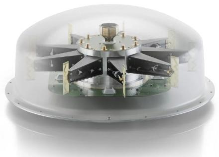
Inside ADFA 2: circular antenna arrays with the reference monopole in the centre.
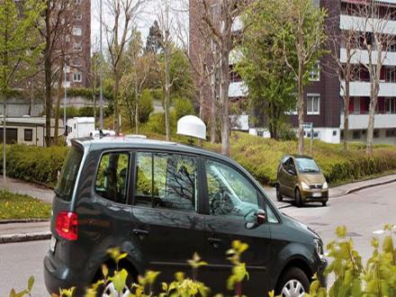
On a vehicle roof with magnetic mount; up to 130 km/h.
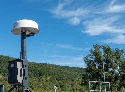
On a mast with the Outdoor Unit as a fixed station.
ADFA 2 specifications
| Parameter | Value |
|---|---|
| DF frequency range | 10 MHz – 8 GHz |
| Monitoring (spectrum) frequency range | 100 kHz – 8 GHz |
| DF method | 10 – 200 MHz: Watson-Watt, two orthogonal crossed loops · 200 MHz – 8 GHz: correlative interferometer, 9-element circular arrays |
| DF accuracy | ≤ 200 MHz: 1.5° RMS (typ.) · > 200 MHz: 1° RMS (typ.) |
| Bearing cycle time | 1.2 ms minimum |
| DF sensitivity | 900 MHz – 1.8 GHz: 1 – 2 µV/m (typ.) |
| IP3 | 200 MHz – 2.7 GHz: +20 dBm (typ.) · 2.7 – 8 GHz: +17 dBm (typ.) |
| Polarization | Vertical |
| Antenna aperture | 200 MHz – 2.7 GHz: Ø 380 mm · 2.7 – 8 GHz: Ø 128 mm |
| Elevation | Calibrated range +40° to −20° |
| Compass | Embedded electronic compass; azimuth uncertainty < 1.5° RMS (typ.) |
| GNSS | Embedded receiver and antenna |
| Dimensions and weight | 219 mm × Ø 480 mm · 6.5 kg |
| Operating temperature | −40 °C to +65 °C |
| Protection class | IP65 |
| Maximum speed / wind | Magnetic vehicle mount: 130 km/h · Mast mount: 275 km/h (no ice), 180 km/h (30 mm ice) |
| Connections | RF: SMA (female), 50 Ω · Control: 12-pin · Powered by the SignalShark |
| Mounting | Mast, tripod (3/8″-16 UNC) or magnetic vehicle mount |
| Part no. | ADFA 2 Basic Set: 3361/101 |
Source: NARDA DF Antennas datasheet (PDF). In urban areas, reflections and multipath can mislead a single bearing; localization therefore relies on combining many bearings taken while moving.
Handheld direction finding antennas
The automatic antenna gets you as far as a vehicle can go; the last hundred metres are usually covered on foot. The handheld antennas plug into the Active Antenna Handle. The handle contains a switchable preamplifier and a 3D electronic compass: as you turn the antenna, azimuth, elevation and polarization are passed to the instrument and the bearing is entered on the map. With the Horizontal Scan option, one turn on the spot draws the signal level as a polar diagram and shows the direction.

Active Antenna Handle
3300/10 · 8 kHz – 8 GHz
Preamplifier with typ. 16 dB gain and noise figure below 6 dB; can be switched off. Compass azimuth uncertainty better than 1.5° RMS for tilt up to 15°. Combined RF and control cable, 1 m; tripod thread (1/4″). 470 g. Powered by the basic unit.

Directional antennas and loop antenna
8 kHz – 8 GHz, four antennas
Loop antenna 8 kHz – 30 MHz, directional antenna 1: 20 – 250 MHz, directional antenna 2: 200 – 500 MHz, directional antenna 3: 400 MHz – 8 GHz. Each weighs 300 – 400 g. With the antenna adapter (N male) you can use your own antenna with the handle’s compass and preamplifier.

DF Downconverter Antenna
7 – 26.5 GHz
Extends SignalShark’s direction finding coverage to 26.5 GHz. Integrated LNA and downconverter; antenna gain up to 20 dBi; electronic compass plus tilt and polarization sensors; IP54 enclosure. Powered directly by the SignalShark, no extra batteries. For interference on satellite links, radar and microwave links. Detailed specifications will be published by the manufacturer at a later date.
| Antenna | Frequency | Type | Antenna factor (passive, typ.) | Dimensions | Weight | Part no. |
|---|---|---|---|---|---|---|
| Loop antenna (H-field) | 8 kHz – 30 MHz | Shielded loop antenna | 66.0 at 100 kHz · 47.5 at 1 MHz · 42.0 above 10 MHz, dB(1/m) | 430 × 370 × 42 mm | 380 g | 3100/14 |
| Directional antenna 1 | 20 – 250 MHz | Directional loop antenna | 21 dB(1/m) at 200 MHz | 325 × 255 × 80 mm | 400 g | 3100/11 |
| Directional antenna 2 | 200 – 500 MHz | Directional dipole antenna | 21 dB(1/m) at 350 MHz | 285 × 410 × 43 mm | 300 g | 3100/12 |
| Directional antenna 3 | 400 MHz – 8 GHz | Log-periodic antenna | 18.5 dB(1/m) at 500 MHz | 478 × 332 × 50 mm | 350 g | 3100/13 |
| Active Antenna Handle | 8 kHz – 8 GHz | Handle with preamplifier and compass | — | 165 × 165 × 43 mm | 470 g | 3300/10 |
| Antenna adapter | — | N male; for third-party antennas | — | — | — | 3100/15 |
| Arm support | — | For the Active Antenna Handle | — | — | — | 3100/90.10 |
| Three-axis E-field antenna | 200 MHz – 8 GHz | Isotropic; for exposure measurement | — | — | — | 3502/03 |
Operating temperature of the handheld antennas: −10 to +55 °C. Source: NARDA DF Antennas datasheet.
Software options
The basic set includes the 40 MHz real-time spectrum, markers and the peak table. Other functions are added as options and can be enabled later, so you buy only what you need. Several views can be open on the display at the same time.
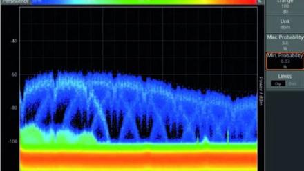
Persistence
Frequency of occurrence in the real-time spectrum
Displays level versus frequency, with colour indicating how often each point occurs. A weak or short signal hidden under a strong emission becomes visible in this view.

Spectrogram
Waterfall diagram
Shows how the spectrum changes over time; ideal for long-term monitoring. The smallest selectable time resolution is 31.25 µs. Works in both the real-time and the scan spectrum.

Automatic DF Antenna Control, Bearing View
Bearing display for ADFA 2
Azimuth, elevation, bearing quality and omnidirectional RMS level on one screen. This option controls the ADFA 2.

Mapping and Localization
Map and heat map
Automatically evaluates all available bearings and shows them on a map; the probable transmitter position appears as a heat map. You can also load your own maps.

Horizontal Scan
Polar diagram with a handheld antenna
Plots signal strength against angle of incidence in a polar diagram. Used to take a bearing by turning once with a handheld directional antenna.

Level Meter and Analog Demodulation
Selective measurement and listening
The Level Meter measures selectively at a defined frequency with a channel bandwidth of 25 Hz – 40 MHz, including compass values. Analog Demodulation adds AM, FM, PM, SSB, CW, pulse and IQ demodulation with squelch and AGC.
| Option | What it provides | Part no. |
|---|---|---|
| 40 MHz real-time Spectrum, Marker, Peak Table | Included in the basic set | 3310/95.001 |
| Spectrogram | Waterfall diagram in real-time and scan spectrum | 3310/95.002 |
| Level Meter (incl. compass values) | Selective level measurement at one frequency; CBW 25 Hz – 40 MHz | 3310/95.003 |
| Persistence | Colour-coded frequency of occurrence in the real-time spectrum | 3310/95.004 |
| Automatic DF Antenna Control, Bearing View | ADFA 2 control and bearing display | 3310/95.005 |
| Mapping and Localization | Evaluation of bearings on a map, heat map | 3310/95.006 |
| Analog Demodulation | AM, pulse, CW, ISB, USB, LSB, FM, PM, IQ; squelch and AGC | 3310/95.007 |
| Horizontal Scan | Polar diagram with a handheld antenna | 3310/95.011 |
| SCPI Remote Control | Remote control with a standard command language | 3310/95.012 |
| VITA 49 | Packet-based streaming of IQ and spectrum data | 3310/95.014 |
| IQ Analyzer, Recorder, Trigger, Magnitude View | IQ recording, triggering and detailed analysis | 3310/95.018 |
| SignalShark 5G Analyzer Measurement | 5G measurement, extrapolation to maximum load | 3310/95.020 |
| 4G EMF Decoder | Decoder for exposure measurement of 4G signals | 3310/95.021 |
| 5G EMF Decoder | Decoder for exposure measurement of 5G signals | 3310/95.022 |
| SignalShark 5G Analyzer Software | PC software | 3300/93.12 |
| SignalShark Tools | Configuration software; free download | 3300/93.01 |
The Outdoor Unit basic sets also include SCPI Remote Control. Source: NARDA SignalShark datasheets.
IQ Analyzer: analysis down to nanoseconds
The hardest signals in interference hunting are weak, sporadic and hidden under other emissions. The IQ Analyzer option records IQ data with up to 40 MHz bandwidth and lets you change time and frequency resolution after the measurement: time resolution down to 20 nanoseconds, frequency resolution down to 25 Hz.
- Recording: 1.6 GB ring memory; a 40 MHz channel is recorded gap-free for 5 seconds
- Views: spectrum, spectrogram, magnitude versus time and persistence, all on the same recording
- Triggering: level, time, GPS and gated trigger
- Time-gated measurement: start, stop, offset and period are adjustable; in time-division systems such as 5G and DECT only the relevant time slot is measured
- Eight markers for measuring and classifying signals
- Export: HDF5 format
- 100% POI: signals longer than 1.41 µs at CBW 40 MHz
Runs on all housing versions; requires firmware 1.9.0 and operating system V2.0.6 or higher. It can be installed on existing devices on site or remotely.

IQ Analyzer: spectrum, spectrogram, magnitude and persistence views on the same recording.

5G Analyzer: decoding of 5G NR signals and extrapolation to maximum load.
Python scripts: Narda Script Launcher
SignalShark runs Python. NARDA provides ready-made scripts (NSL) for common tasks; you can use them as they are, modify them or write your own.
| Script | What it does |
|---|---|
| NSL Remote DF (Net DF) | Localization with several SignalShark devices on a network |
| NSL Coverage Map | Location-dependent level measurement with a colour-coded coverage map; drive test |
| NSL Autopilot | Sends the point indicated by the heat map to a navigation device as the destination |
| NSL Channel Scanner | Monitors predefined channels in sequence (memory / frequency scan) |
| NSL Limit Line | Triggers on a limit line in the spectrum |
| NSL GNSS | Shows GNSS reception status and issues a warning |
| NSL MS Word | Generates a measurement report from a Word template |
| NSL IQ Recorder | Records IQ data in WAV format |
| NSL Converter | Format conversion, e.g. HDF5 to CSV |
| NSL Tools | Copy settings, save the peak table as CSV, IQ stream control, peak trigger and similar utilities |
Third-party software also runs directly on the device or via VITA 49 streaming. NARDA’s documentation covers integrations with Decodio (including TDOA) and Procitec go2SIGNALS (signal classification and decoding).
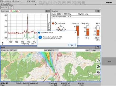
NSL Remote DF: bearings from networked stations are intersected on one map.
Application packages and accessories
NARDA bundles options and accessories by task. Basic set (3310/101): instrument, two batteries, power supply, ferrite clamp, holding strap, touch pen, USB stick and manual.
| Package | Contents | Part no. |
|---|---|---|
| Receiver | Spectrogram + Level Meter + Analog Demodulation | 3310/94.01 |
| Direction Finding Basic | Active Antenna Handle, arm support, Mapping and Localization, Horizontal Scan | 3310/94.02 |
| Automatic DF 2 | ADFA 2, 5 m RF and control cable, Bearing View option, vehicle mounting kit | 3310/94.06 |
| Automatic DF 2, Hardcase | As above + ADFA hardcase | 3310/94.12 |
| Remote Control | SCPI Remote Control + VITA 49 | 3310/94.10 |
| Off-Site Extension | Hardcase, vehicle adapter, external chargers, carrying strap, headphone, screen protector | 3310/94.14 |
| Antenna Basic Kit | Directional antenna 3 + antenna adapter | 3106/92.03 |
| Antenna Extension Kit | Directional antennas 1 and 2 + loop antenna | 3106/92.04 |
Accessories
| Accessory | Description | Part no. |
|---|---|---|
| RF and control cable (for ADFA) | DC – 8 GHz, N to SMA, 50 Ω; 5 m / 10 m / 15 m | 3603/02 / 3603/07 / 3603/03 |
| ADFA vehicle mounting kit | Magnetic | 3300/90.04 |
| ADFA mast mounting kit | Non-conductive | 3300/90.23 |
| Tripod (for ADFA 2) | Non-conductive, 1.65 m, reinforced, 3/8-inch-16 UNC | 3300/90.16 |
| Tripod quick-release coupling | 3/8-inch-16 UNC | 3300/90.17 |
| Tripod (for handheld antennas) | Non-conductive, 1.65 m, 1/4 inch, with bag | 2244/90.31 |
| ADFA hardcase | Transport case | 3360/90.01 |
| SignalShark 3310 hardcase | Transport case; IP67 inside | 3310/90.05 |
| External GNSS antenna | Active | 3300/90.05 |
| RF adapter | N male to SMA female, 50 Ω | 3300/90.13 |
| Battery pack set | 2 × Li-Ion, 7.5 V, 6.4 Ah | 2259/92.16 |
| External double charger set | 2 × single-bay charger | 2259/92.17 |
| Vehicle power adapter | DC, 100 W | 2259/92.35 |
| Power supply | 12 VDC, 5.5 A; 100 – 240 VAC | 2259/92.09 |
| Carrying strap | For the basic unit | 3300/90.08 |
| Headphone | 3.5 mm | 3300/90.14 |
| Screen protector film | 10.4 inch | 3310/90.04 |
| 19-inch rack mounting kit | For Remote Unit 332x | 3320/90.05 |
Spectrum monitoring and direction finding: a short guide
Six concepts are enough to choose the right configuration.
Real-time or scan?
In real-time mode the 40 MHz band is processed continuously; no instant is missed. In scan mode the instrument moves that 40 MHz window quickly across a wider band and returns to each frequency at intervals. If you know which band the short signal is in, use real-time; if not, start with a scan.
Probability of intercept (POI)
States how long a signal must last to be displayed at its full level. It depends on RBW, sampling rate, FFT window length and overlap. For SignalShark it is 3.125 µs at RBW 800 kHz; shorter signals are still seen, but their level reads low.
Why dynamic range matters
In a city the interferer is usually right next to strong base station and broadcast signals. Intermodulation products generated inside the receiver look like real signals. Preselector filters, high IP3 and a low noise floor together allow a weak signal to be told apart from spurious products.
Correlative interferometer and Watson-Watt
The correlative interferometer compares phase differences between the elements of a circular array with stored reference data; it is accurate at higher frequencies. Watson-Watt derives the direction from the amplitude ratio of two orthogonal loops, which allows a compact antenna at low frequencies where the wavelength is larger than the antenna.
Angle of arrival (AoA) and TDOA
With AoA each station delivers a bearing; the intersection of two or more bearings gives the position. It also works with a single moving vehicle. With TDOA at least three stations measure the time difference of arrival; the antenna is simple, but precise time synchronization and sufficient signal bandwidth are needed. The two can be combined.
Automatic or manual?
An automatic antenna takes hundreds of bearings per second, works on the move and catches short signals; it narrows down a wide area quickly. With a handheld antenna you search for the strongest direction; it is slower, but goes indoors, onto rooftops and wherever a vehicle cannot. In the field the two are usually used one after the other.
Common situations in the field
| Situation | Likely cause | What to do |
|---|---|---|
| An interference complaint, but nothing shows in the spectrum | The signal is short or sporadic; the scan misses it | Use the real-time spectrum and Persistence; record over a long period with the Spectrogram |
| Another signal is suspected under a strong emission | They overlap in the spectrum | Check frequency of occurrence in the Persistence view; separate them in the time domain with the IQ Analyzer |
| Signals appear on screen that are not real | A very strong nearby transmitter overloads the input (intermodulation) | Increase attenuation; if the signal drops disproportionately it is spurious. Switch off the preamplifier |
| Bearings are scattered in a city | Reflections and multipath | Collect many bearings while moving and rely on the heat map; measure from high, open locations |
| Close to the source, but the automatic antenna gives no direction | Very short distance, source inside a building | Switch to a handheld directional antenna and Horizontal Scan; follow the level |
| The source is below 30 MHz | Long wavelength; line-borne or equipment-borne interference | Follow the magnetic field with the loop antenna; approach cables and equipment and track the level |
| Interference above 8 GHz (satellite, radar, microwave link) | Outside SignalShark’s direct range | Use the DF Downconverter Antenna (7 – 26.5 GHz) |
| The signal exists only in certain time slots (TDD, DECT) | Time-division system | Use time-gated measurement in the IQ Analyzer |
| No data from an unattended station | No network connection | Consider the Outdoor Unit model with modem, or single-cable supply with PoE++ |
| The battery runs out in the field | About 3 hours of operating time | Batteries are hot-swappable; carry a spare battery set and the vehicle adapter |
Frequently asked questions
What is a radio monitoring and localization system?
An instrument that finds a signal in the radio spectrum, analyzes its properties and determines the position of its transmitter by direction finding. It is also called an interference and direction analyzer or a transmitter locator.
What is SignalShark?
NARDA SignalShark is a spectrum analyzer, monitoring receiver and direction finding system covering 8 kHz to 8 GHz with 40 MHz real-time bandwidth. It detects and analyzes radio signals and locates their source with automatic or handheld direction finding antennas.
Over which frequency range does it find direction?
10 MHz – 8 GHz with the automatic antenna ADFA 2; 8 kHz – 8 GHz with the handheld antennas; 7 – 26.5 GHz with the DF Downconverter Antenna.
How accurate is the direction finding?
According to the ADFA 2 datasheet, typically 1° RMS above 200 MHz and typically 1.5° RMS at 200 MHz and below. In real terrain reflections affect this value; localization relies on combining many bearings on the map, not on a single bearing.
How short a signal can it capture?
In the real-time spectrum, signals longer than 3.125 µs at RBW 800 kHz are captured with 100% probability at full level. With the IQ Analyzer option this is 1.41 µs; on a recording, time resolution goes down to 20 ns.
Can one device find a position, or are several stations needed?
With a single device and ADFA 2, bearings taken while the vehicle moves are combined on the map to find the position. Where several fixed stations exist, the NSL Remote DF script intersects the bearings of the networked devices on one map.
Is it used for drone detection?
Yes. The radio links between a drone and its remote control are monitored passively and their direction is found; because the instrument does not transmit, it cannot be detected itself. NARDA has application notes on this subject. SignalShark detects and finds direction; it does not jam or neutralize.
What is the difference between the XT and the standard model?
XT models are offered for the rack (3321), outdoor (3331) and module (3341) versions. They provide a more powerful processor, more memory and storage, 2.5 Gigabit Ethernet and higher-rate IQ streaming; the RF performance is the same.
Can we run our own software on it?
Yes. The device runs Windows; you can write Python scripts, control it via SCPI and take IQ data into your own system via VITA 49. The DF Receiver Module is designed specifically for embedding in other systems.
Can it be used for EMC pre-compliance measurements?
The instrument includes CISPR detectors (quasi-peak, C-RMS, C-Avg) and EMC filter bandwidths. These are useful for preliminary investigation and field measurements; accredited EMC testing requires the fully compliant receiver and test set-up specified by the standard.
Is the NARDA IDA 2 (IDA-3106) still available?
No. The IDA 2 has been discontinued; SignalShark is its successor. SignalShark offers a wider frequency range (up to 8 GHz), 40 MHz real-time bandwidth and an automatic direction finding antenna. According to NARDA’s datasheet the handheld directional antennas and the Active Antenna Handle are shared with the IDA.
What are the delivery time and price?
They depend on version, antennas and options. Tell us your task and we will send a suitable configuration and quotation.
Why PROTEL?
| Topic | How |
|---|---|
| Distributorship | General distributor of NARDA Safety Test Solutions for Turkey |
| Configuration | We define the version, antennas, software options and accessories together with you, based on your task |
| Portfolio | Alongside SignalShark, NARDA’s electromagnetic field measurement instruments |
| Calibration, service, training | See our engineering, service, calibration and training page or contact us |
| Sales territory | Turkey, for NARDA products |
Request a NARDA SignalShark quotation
To propose the right configuration quickly, please tell us:
- Task — interference hunting, spectrum monitoring, direction finding, signal analysis, drone detection…
- Frequency range — the bands of interest; whether you need coverage above 8 GHz
- Mode of use — handheld, in a vehicle, in a rack, fixed outdoors or embedded in your own system
- Direction finding — automatic (ADFA 2), handheld antennas or both; number of stations
- Analysis needs — IQ recording, demodulation, 5G, long-term recording
- Integration — SCPI, VITA 49, your own or third-party software
- Power and connectivity — battery, vehicle, PoE, modem
- Quantity; whether training is required
E-mail: [email protected] · Phone: +90 212 221 80 60 · WhatsApp: +90 532 265 91 99
Documents
- Datasheets: Handheld 3310 · Remote Unit 332x · Outdoor Unit 333x · DF Receiver Module 334x · DF antennas · SignalShark EMF
- NARDA pages (brochures, application notes and software downloads): SignalShark · ADFA 2 · DF Downconverter Antenna · manual antennas · options and scripts · IQ Analyzer
Related pages
- NARDA FieldMan EMR meter
- NARDA EMF monitors: personal RF monitors and 24/7 area monitors
- Electromagnetic field (EMF) measurement
- Spectrum analyzers
- Engineering, service, calibration, training
- NARDA products
Product images and product technical information on this page are © Narda Safety Test Solutions GmbH and are used with the manufacturer’s permission. Technical values are taken from the manufacturer’s datasheets; the current datasheet is binding. Source: narda-sts.com